Vlasov2d
This example is compatible with 1.0.6dev (22 February 2017).
This simulation is a modification of the vlasov2d test (tests/vlasov2d.cpp). It finds out how a 3 keV, 5 mA/cm2 H+ beam behaves in a system of three electrodes. For simulating this problem a program needs to be written in C++ to control the IBSimu library that you have installed. Therefore you need to write a C++ file, named vlasov2d.cpp for example.
First of all your program needs to access the the IBSimu library. For this you need to include some header files in your cpp-file:
#include "epot_bicgstabsolver.hpp"
#include "geometry.hpp"
#include "func_solid.hpp"
#include "epot_efield.hpp"
#include "meshvectorfield.hpp"
#include "particledatabase.hpp"
#include "geomplotter.hpp"
#include "ibsimu.hpp"
#include "error.hpp"
The needed include files depends on the functions and classes that are used by your program. More information can be found in the reference manual. Then you program need to have a main function as an entrance point to the program:
int main( int argc, char **argv )
{
    try {
	ibsimu.set_message_threshold( MSG_VERBOSE, 1 );
	ibsimu.set_thread_count( 4 );
        simu();
    } catch ( Error e ) {
        e.print_error_message( ibsimu.message( 0 ) );
        exit( 1 );
    }

    return( 0 );
}
In here we are using the try-catch environment of C++ that will catch errors within the IBSimu library and present some sensible error message. The error message will include the source file, line number and the name of the function where the error happened in addition to the message itself. The ibsimu is a global object that can be used to control some basic parameters of the code. The function set_message_threshold() is used to set the amount of output printed to stdout (or output file) by the library functions. Zero means no output, one is standard output, two is extended output. The target for library messages can be set using function set_message_output() of the ibsimu object. Some parts of IBSimu can use multiple CPUs (or cores) by splitting the calculation into several threads. The number of threads created can be set using set_thread_count().
Next we write the simu() function, the actual workhorse of the simulation. First we need to define the geometry where the simulation is done:
Geometry geom( MODE_2D, Int3D(241,101,1), Vec3D(0,0,0), 0.0005 );
The first argument specifies that the simulation is planar two dimensional. Other possibilities would be MODE_1D for one dimensional simulations, MODE_CYL for cylindrically symmetrical simulations and MODE_3D full three dimensions. The second argument defines the size of the simulation mesh. In this case it is 241 nodes along x-axis and 101 nodes along y-axis and 1 node along z-axis. The third argument specifies the location of the node (0,0,0) in meters. The fourth argument defines the size of mesh, meaning the length from one node to the next in meters. The size of the simulation area is therefore 240x0.5 mm by 100x0.5 mm.
Next we need to define the electrodes in the geometry. There are several ways of defining them. In this example we will use the most fundamental way, the FuncSolid objects. Other ways include Constructive Solid Geometry definition, two dimensional DXF-file based definition and three dimensional STL-files. With FuncSolid you need to write a function, which takes in the coordinates of a point and returns true if the point is inside the solid and false otherwise. In this example we have three electrodes. First we need to define the functions:
bool solid1( double x, double y, double z )
{
    return( x <= 0.02 && y >= 0.018 );
}


bool solid2( double x, double y, double z )
{
    return( x >= 0.03 && x <= 0.04 && y >= 0.02 );
}


bool solid3( double x, double y, double z )
{
    return( x >= 0.06 && y >= 0.03 && y >= 0.07 - 0.5*x );
}
The FuncSolid objects have to be defined and inserted in the geometry:
Solid *s1 = new FuncSolid( solid1 );
geom.set_solid( 7, s1 );
Solid *s2 = new FuncSolid( solid2 );
geom.set_solid( 8, s2 );
Solid *s3 = new FuncSolid( solid3 );
geom.set_solid( 9, s3 );
First the FuncSolid object is made using the new operator of C++. This object is then inserted in the geometry using set_solid function. The set_solid function is given the number of the electrode, which is used to reference the electrode. These numbers start from 7 for the user defined electrodes, because numbers from 1 to 6 are used to reference the boundaries of the simulation box.
Now that the geometry is defined, the potentials of the electrodes and the boundary conditions for the simulation box have to be defined. The electrode numbers will be used to reference the different boundaries. Electrode 1 is the minimum x boundary, 2 is maximum x boundary, 3 is minimum y, 4 is maximum y, 5 is minimum z and 6 is maximum z. Starting from 7 you reference to the user defined electrodes. The simulation box boundaries can have either Neumann or Dirichlet boundary condition. Neumann means constant first derivative of the potential with respect to the unit outward normal of the surface. Dirichlet means constant potential on the surface. User defined electrodes can only have Dirichlet boundary condition. In our example we define as follows:
geom.set_boundary( 1, Bound(BOUND_DIRICHLET,  -3.0e3) );
geom.set_boundary( 2, Bound(BOUND_DIRICHLET,  -1.0e3) );
geom.set_boundary( 3, Bound(BOUND_NEUMANN,     0.0  ) );
geom.set_boundary( 4, Bound(BOUND_NEUMANN,     0.0  ) );
geom.set_boundary( 7, Bound(BOUND_DIRICHLET,  -3.0e3) );
geom.set_boundary( 8, Bound(BOUND_DIRICHLET, -14.0e3) );
geom.set_boundary( 9, Bound(BOUND_DIRICHLET,  -1.0e3) );
In the example we set a fixed -3 kV potential on the xmin boundary, -1 kV potential on the xmax boundary and standard Neumann boundary condition (zero first derivative of potential) on ymin and ymax boundaries. The user defined electrodes get -3 kV, -14 kV and -1 kV potentials. After these definitions we can build the mesh:
geom.build_mesh();
This function maps the simulation area and finds where the electrode boundaries are. Then we are ready to formulate the problem of solving the Poisson equation. The problem is contained in the EpotSolver object, in this case we use the EpotBiCGSTABSolver:
EpotBiCGSTABSolver solver( geom );
In this example we use the default stablized bi-conjugate gradient iterative solver. It is included with IBSimu and doesn't depend on any external libraries. For 2D problems the most efficient solver currently is the UMFPack solver but it is dependen't on the external SuiteSparse library and it's existence depends on the parameters given for the compiler during the compilation of the library.
After this we initialize some other object that will be needed in the calculation:
EpotField epot( geom );
MeshScalarField scharge( geom );
MeshVectorField bfield;
EpotEfield efield( epot );
field_extrpl_e efldextrpl[6] = { FIELD_EXTRAPOLATE, FIELD_EXTRAPOLATE,
                                 FIELD_SYMMETRIC_POTENTIAL, FIELD_EXTRAPOLATE,
                                 FIELD_EXTRAPOLATE, FIELD_EXTRAPOLATE };
efield.set_extrapolation( efldextrpl );
The object names are rather self-explanatory: MeshScalarField is a mesh-based scalar field in the geometry of geom. We use it for storing electric potential and space charge density fields. The particle calculation also need a magnetic field (even if it is zero). The mesh of the magnetic field is not bound to the mesh of the electric field and therefore it doesn't use a lot of memory if it is a constant field. The magnetic field is of course a MeshVectorField. The electric field EpotEfield is a special object, which doesn't contain any data on it's own. It is used to calculate the electric field at a location from the electric potential data. The electric field is told what is returned for the electric field outside the simulation geometry. This is needed for the particle calculations close by to the boundaries. In this example the geometry is symmetrical so we define the ymin boundary to mirror the efield.
Before getting into the vlasov iteration loop we still need to define the particle calculation system, the ParticleDataBase:
ParticleDataBase2D pdb( geom );
bool pmirror[6] = { false, false, true, false, false, false };
pdb.set_mirror( pmirror );
The particle calculation object needs to be selected according to the geometry of the simulation. In this case we use the ParticleDataBase2D because the geometry is two dimensional. By default, the particles, which hit the simulation boundaries are removed from the simulation. In case of symmetrical simulations it might be useful to have particles mirrored at boundaries. This can be set using set_mirror(). The last parameter set in the particle database is the type of interpolation used. The iterator calculates the particle trajectory in discrete steps.
Then we are finally ready to start the Vlasov iteration to find a self-consistent solution for the electric potential and beam propagation in the geometry. This is achieved by first solving the electric potential in the geometry without the beam (zero space charge, which is the default condition for the MeshScalarField scharge). The electric field is then calculated from the electric potential with efield.recalculate(). Then the beam particles are iterated through the geometry and space charge from the beam is calculated. This space charge is then used to calculate the next iteration of electric potential field. This is repeated until convergence. In the example we do 5 such loops:
for( size_t i = 0; i < 5; i++ ) {
    solver.solve( epot, scharge );
    efield.recalculate();
    pdb.clear();
    pdb.add_2d_beam_with_energy( 1000, 50.0, 1.0, 1.0,
                                 3.0e3, 0.0, 0.0,
                                 0.0, 0.0,
                                 0.0, 0.012 );
   pdb.iterate_trajectories( scharge, efield, bfield );
}
The particle beam in this example is defined using the function add_2d_beam_with_energy(). The first argument for the function specifies the number of particle trajectories defined. Typically the number of particle trajectories has to be enough to represent the total beam well enough within each mesh square. In this case we have no temperature distribution (zero emittance) in the beam so quite a small number of trajectories is enough. In this case we have 1000 trajectories, which is about 40 trajectories per mesh unit. The rest of the function arguments specify the current density of the beam (A/m2), particle charge (in electron charges), particle mass (in atomic units), starting energy (eV), parallel tempererature (eV), transverse temperature (eV), x1, y1, x2 and y2 coordinates of the starting line, where the beam starts from (meters).
After sufficient amount of iteration loops the solution has hopefully converged. Sometimes it is necessary to use under-relaxation techniques for the space charge field to have convergence. Unstabilities are most likely encountered when beam intensity is close to being space charge limited.
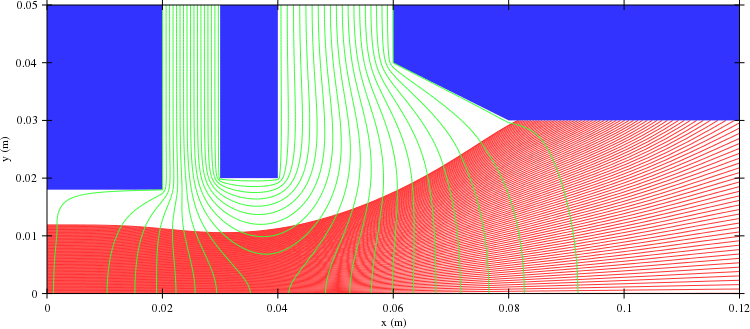
After the loops we plot the results. Of course you could (or should) also make plots during the iteration to verify that the solution converges. In this case we only plot a simple geometry plot showing the geometry, the beam and the electric field using equipotential lines:
GeomPlotter geomplotter( geom );
geomplotter.set_size( 750, 750 );
geomplotter.set_epot( &epot );
geomplotter.set_particle_database( &pdb );
geomplotter.plot_png( "plot1.png" );
OK. That is it. The complete source file is available here: vlasov2d.cpp. You also a need a Makefile to build the simulation executable. The resulting plot file showing the system follows:

